Create your own ambilight solution
Ambilight is a technology of Bias lighting used in Phillips TVs which illumitates the back of your tv with colors related to the image displayed. Their solution is expensive, but you can create your own solution using an ESP 8266 controller and some cheap led strips.
In order to adapt the lights to the image, the ambilight system needs to capture the images displayed on your tv. There are 2 main ways to do that: you can use a physical box to capture the video using an HDMI splitter and an acquisition card between your devices (Mi Box, Nvidia Shield, Xbox …) and your TV or you can use a software solution to directly stream the video from a device (PC, Android TV …).
First Method
My first attempt was with the fist method (which was at that time the most used). The advantages are that you don’t need to install a third-party software in order to connect a device to your ambilight. You only need to plug the HDMI output in the splitter and it should work. You can even connect an HDMI switch before the splitter to connect multiple devices to your amblight system.
However a stream may be protected with HDCP: a DRM protection which prevents it from being recorded, but there are many flaws in this technology and you can find some cheap HDMI splitters or HDMI-to-RCA converters from China that are able to strip the HDCP to obtain a readable stream.
You then need to capture and process the video signal, for this task I used an RCA-to-USB key (the image quality isn’t important as the image is only used to detect the colors on the borders of the image). I used a Raspberry PI B+ to process the image and an arduino to control the led strips. The schema looked like this:
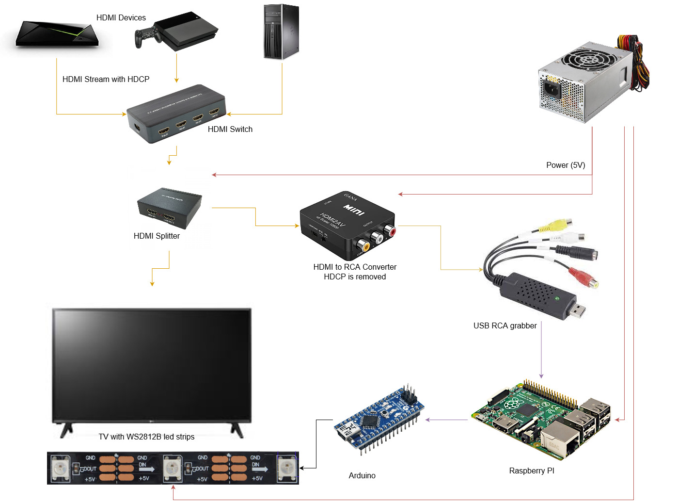
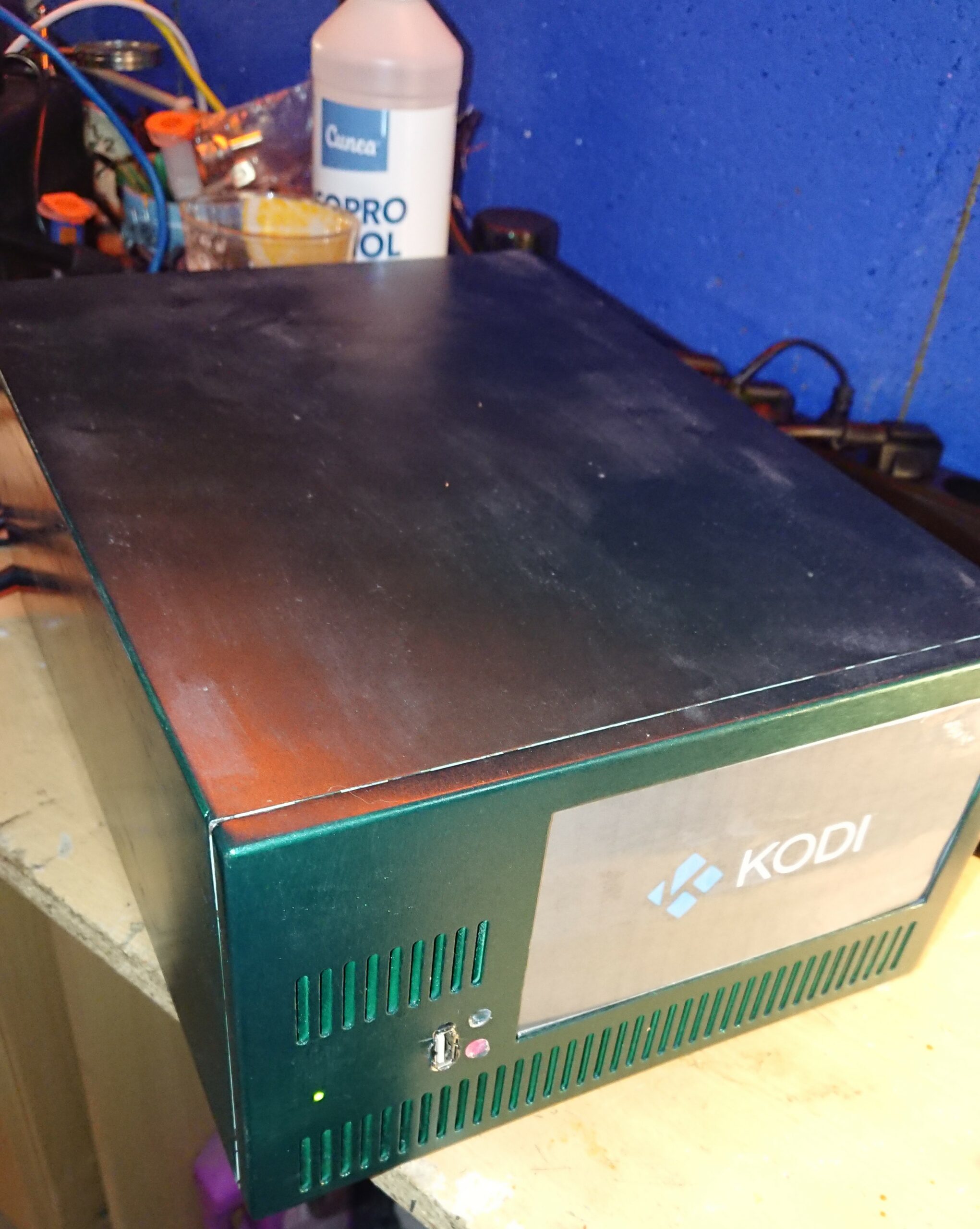
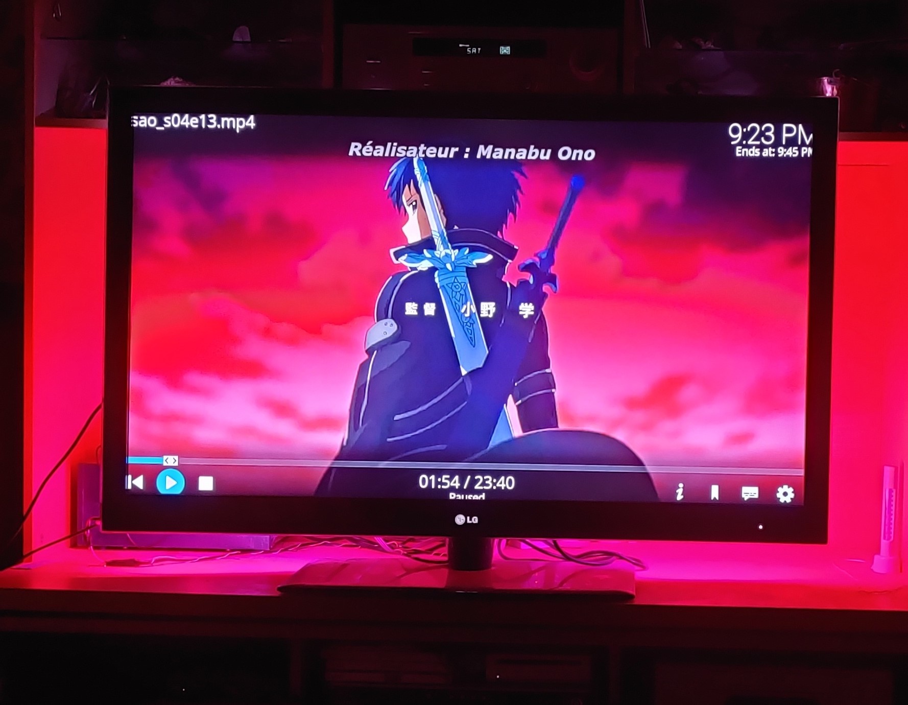
I then sticked some WS2812B led strips behind the TV and renovated an old metal box to fit all the components for the ambilight system. This box already had an integrated power supply that I used to power the raspberry pi and the leds in 5V.


On the software side, I used Hyperion (the first version) and the Hypercon.jar program to create the configuration file. The Raspberry PI would then send the orders to the connected arduino card that controlled the leds.
This method worked pretty well but the box was pretty big and when I moved in, I didn’t have it on hand (nor did I have the necessary components to build a new one). So I decided to try another method.
Second Method
Presentation
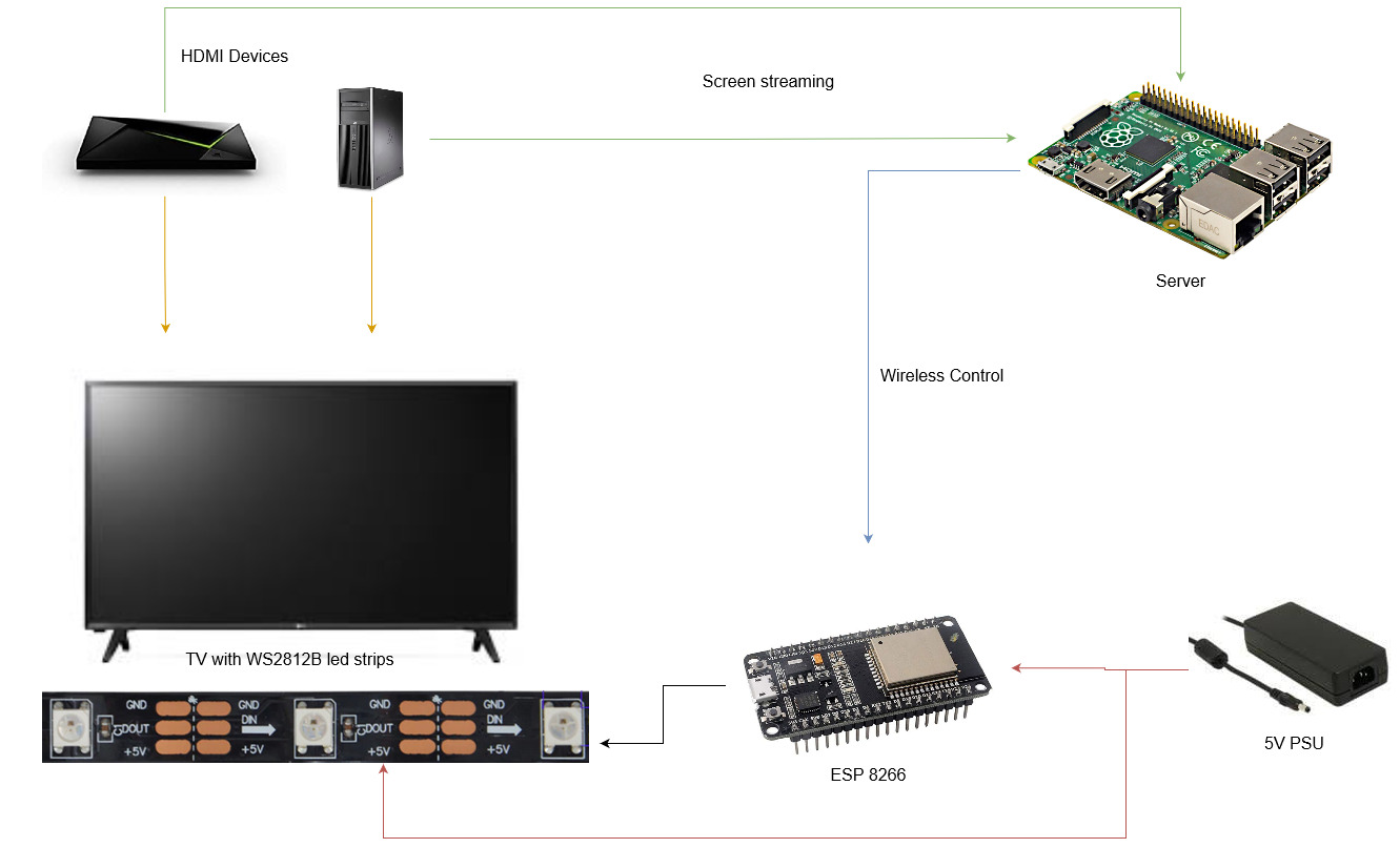
With this second solution, the splitter, converter and grabber are no longer needed: I just connect the HDMI devices directly to my tv and these devices will stream their video to an external server with Hyperion-ng (a new version of hyperion) which will send led control commands to an ESP 8266 over wifi (using E 1.31). Note that with this version, it will be impossible to capture DRM protected content.
Configuration of the Hyperion Clients
To stream the video feed from my android tv box, I used the hyperion-android-grabber app and for my PC I used the HyperionScreenCap software.
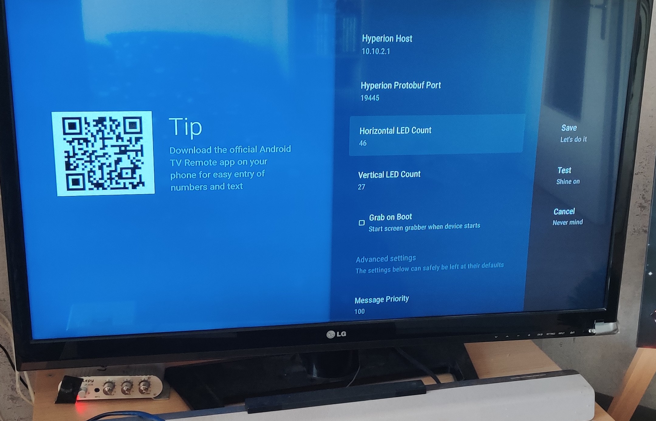
To install a third-party apk on android tv, you need to enable ADB in the developer settings and connect to your box from your PC with adb connect 192.168.1.X You can then type adb install ./tv-release.apk to install the apk on your box. The app sould appear in your applications menu, if this is not the case, you can launch it manually with adb shell am start -n com.abrenoch.hyperiongrabber/.tv.activities.MainActivity. You can then go in the app’s settings and configure the IP of your server and the protobuf port (that will be used to receive the video from the box). You also need to set the priority between 100 and 199.
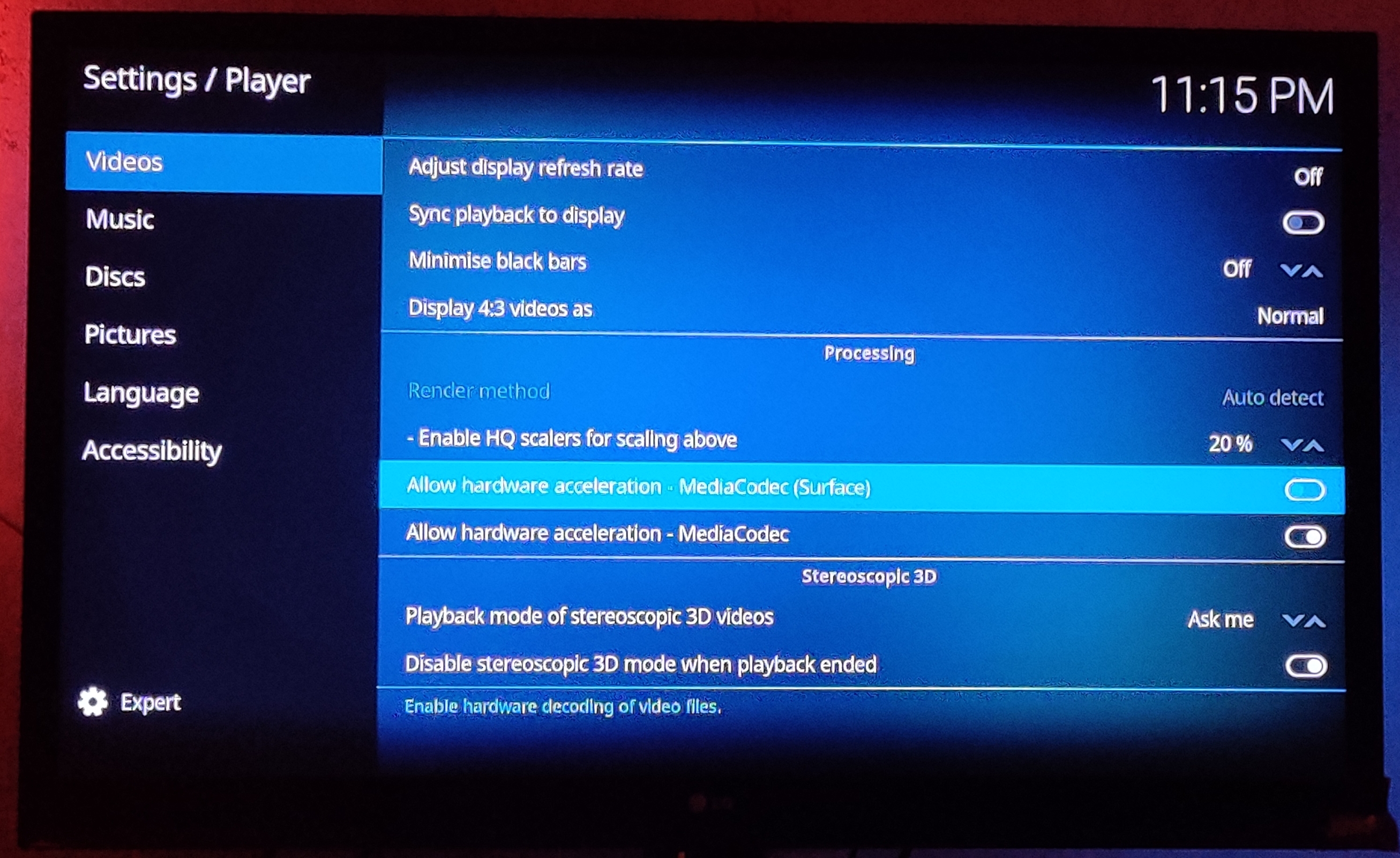
For android tv, you may need to disable some hadware acceleration features that prevents the image from being captured, for Kodi, you need to disable the MediaCodec (Surface) feature in the settings.
Note that any service serving drm protected content will not work (like Netflix, Amazon Prime, Twitch …). For youtube, you can bypass this protection by using the excellent SmartTube app.
Configuration of the Hyperion Server
Once the clients are configured, you need to setup the hyperion-ng server that will receive the video streams from the clients, process it and send the commands to you leds. You can use the following dockerfile and docker-compose to run it.
FROM debian:11-slim
RUN apt-get update && apt-get install -y \
  wget jq \
  qtbase5-dev \
  libqt5serialport5-dev \
  libqt5sql5-sqlite \
  libqt5svg5-dev \
  libqt5x11extras5-dev \
  build-essential \
  libusb-1.0-0-dev \
  libcec-dev \
  libavahi-core-dev \
  libavahi-compat-libdnssd-dev \
  libxcb-util0-dev \
  libxcb-randr0-dev \
  libxcb-shm0-dev \
  libxcb-render0-dev \
  libxcb-image0-dev \
  libxrandr-dev \
  libxrender-dev \
  libturbojpeg0-dev \
  libssl-dev
RUN wget "https://api.github.com/repos/hyperion-project/hyperion.ng/releases" -O - | jq -r '.[0].assets[] | select(.name | contains("x86_64.deb")).browser_download_url' | wget -i - -O hyperion.deb && dpkg -i hyperion.deb
CMD "/usr/share/hyperion/bin/hyperiond"version: "3"
services:
hyperion:
build: .
volumes:
- /app/docker/data/Hyperion:/root/.hyperion
labels:
- traefik.http.routers.hyperion.rule=Host(`hyperion.domain.tld`)
- traefik.http.routers.hyperion.tls=true
- traefik.http.routers.hyperion.entrypoints=https_lan
- traefik.http.services.hyperion.loadbalancer.server.port=8090
- traefik.enable=true
restart: unless-stopped
ports:
- 19400:19400
- 19444:19444
- 19445:19445
- 19333:19333Configuration of the ESP8266
The last thing to configure is the ESP 8266, that will receive the commands from the Hyperion server (with the E1.31 protocol) and control the leds. To do this easily, we can use ESP Home (see my previous post here). With the basic config, you just need to add a neopixelbus component with the type, command pin and amount of leds, and add the E1.31 effect to allow hyperion to control the leds. While writing the configuration file, I also decided to add an infrared led to control my TV from Home Assistant. For this you can either attach an IR receiver to capture the IR codes from your remote or try to find the codes online. Fom my TV brand (LG) I have found the following gist with all the codes.
esphome:
  name: ambilight
  platform: ESP32
  board: esp32doit-devkit-v1

# Enable logging
logger:

# Enable Home Assistant API
api:

ota:
  password: ""

wifi:
  ssid: !secret "wifi_ssid"
  password: !secret "wifi_password"

  manual_ip:
    static_ip: 10.20.8.2
    gateway: 10.20.1.1
    subnet: 255.255.0.0

  # Enable fallback hotspot (captive portal) in case wifi connection fails
  ap:
    ssid: "Ambilight Fallback Hotspot"
    password: ""

captive_portal:

status_led:
  pin: GPIO4

############################ IR TV ON/OFF #############

remote_transmitter:
  pin: GPIO5
  carrier_duty_percent: 10%

switch:
  - platform: template
    name: "LG Power"
    turn_on_action:
      remote_transmitter.transmit_lg:
        data: 0x20DF10EF
        nbits: 32
  - platform: template
    name: "LG Input"
    turn_on_action:
      remote_transmitter.transmit_lg:
        data: 0x20DFD02F
        nbits: 32
  - platform: template
    name: "LG Input"
    turn_on_action:
      remote_transmitter.transmit_lg:
        data: 0x20DFD02F
        nbits: 32
  - platform: template
    name: "LG Up"
    turn_on_action:
      remote_transmitter.transmit_lg:
        data: 0x20DF02FD
        nbits: 32
  - platform: template
    name: "LG Down"
    turn_on_action:
      remote_transmitter.transmit_lg:
        data: 0x20DF827D
        nbits: 32
  - platform: template
    name: "LG Right"
    turn_on_action:
      remote_transmitter.transmit_lg:
        data: 0x20DF609F
        nbits: 32
  - platform: template
    name: "LG Left"
    turn_on_action:
      remote_transmitter.transmit_lg:
        data: 0x20DFE01F
        nbits: 32
  - platform: template
    name: "LG OK"
    turn_on_action:
      remote_transmitter.transmit_lg:
        data: 0x20DF22DD
        nbits: 32
  - platform: template
    name: "LG Exit"
    turn_on_action:
      remote_transmitter.transmit_lg:
        data: 0x20DFDA25
        nbits: 32
  - platform: template
    name: "LG HDMI1"
    turn_on_action:
      remote_transmitter.transmit_lg:
        data: 0x20DF738C
        nbits: 32
  - platform: template
    name: "LG HDMI2"
    turn_on_action:
      remote_transmitter.transmit_lg:
        data: 0x20DF33CC
        nbits: 32
  - platform: template
    name: "LG HDMI3"
    turn_on_action:
      remote_transmitter.transmit_lg:
        data: 0x20DF9768
        nbits: 32
  - platform: template
    name: "LG Settings"
    turn_on_action:
      remote_transmitter.transmit_lg:
        data: 0x20DFC23D
        nbits: 32
  - platform: template
    name: "LG Vol+"
    turn_on_action:
      remote_transmitter.transmit_lg:
        data: 0x20DF40BF
        nbits: 32
  - platform: template
    name: "LG Vol-"
    turn_on_action:
      remote_transmitter.transmit_lg:
        data: 0x20DFC03F
        nbits: 32
  - platform: template
    name: "LG Mute"
    turn_on_action:
      remote_transmitter.transmit_lg:
        data: 0x20DF906F
        nbits: 32
  - platform: template
    name: "LG 3D"
    turn_on_action:
      remote_transmitter.transmit_lg:
        data: 0x20DF3BC4
        nbits: 32

########################## LEDs #####################
e131:
  method: multicast # default: register E1.31 to Multicast group

wled:

light:
  - platform: neopixelbus
    type: GRB
    pin: GPIO18
    num_leds: 146
    name: "TV LEDs"
    variant: WS2812
    effects:
      - e131:
          universe: 1
          channels: RGB
      - wled:
          port: 21324

On a side note, if like me you are using an ESP-32, you can add the following code to your esp configuration to make it capable of acting as a bluetooth relay for Home-Assistant.
esp32_ble_tracker:
  scan_parameters:
    interval: 1100ms
    window: 1100ms
    active: true

bluetooth_proxy:
Configuration of Home Assistant (Optional)
You should now be able to add all the esp home devices in Home Assistant. You can see below that I also configured the Hyperion integration. We now have a complete remote to control our tv thanks to the IR led and a light entity representing our led strip that we can use to either use like a normal color bulb, set it in E1.31 mode to allow hyperion to control it, or set it in WLED mode to allow it to sync with other wled devices (using the Effect menu).
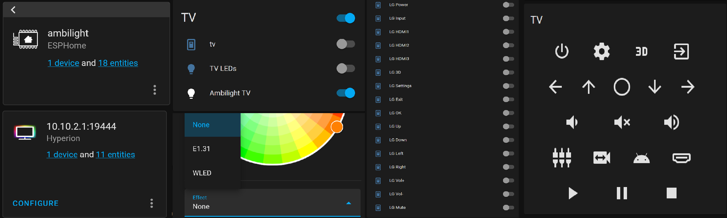
You can also see a TV switch in Home Assistant. I created this device to be able to switch the tv on and off using the IR code corrsponding to the “power” button on the remote and based on the TV’s status on the network (as you can see in the tv’s picture above this TV has an ethernet port, so if the TV is on, then we can ping its IP address). Here is the configuration used to create this device:
switch:
  - platform: template
    switches:
      tv:
        value_template: "{{ is_state('binary_sensor.tv_status', 'on') }}"
        turn_on:
          service: switch.turn_on
          data_template:
            entity_id: >
              {% if is_state('binary_sensor.tv_status', 'off') %}
              switch.lg_power
              {% else %}
              null
              {% endif %}
        turn_off:
          service: switch.turn_on
          data_template:
            entity_id: >
              {% if is_state('binary_sensor.tv_status', 'on') %}
              switch.lg_power
              {% else %}
              null
              {% endif %}

binary_sensor:
  - platform: ping
    host: 10.20.4.2
    name: tv_status
    count: 2
    scan_interval: 10
On the right, you can see a custom card for controlling the TV with a more user-friendly UI. This card (usernein/tv-card) is available on HACS. I used the following configuration (the last row is for controlling a media_player entity, here my kodi instance):
type: custom:tv-card
entity: media_player.tv
title: TV
power_row:
  - lg_power
  - lg_settings
  - lg_3d
  - lg_exit
channel_row:
  - lg_left
  - lg_up
  - lg_ok
  - lg_down
  - lg_right
apps_row:
  - lg_vdw
  - lg_mute
  - lg_vup
nav_row:
  - lg_3d
source_row:
  - lg_input
  - lg_h1
  - lg_h2
  - lg_h3
media_control_row:
  - kodi_play
  - kodi_pause
  - kodi_stop
custom_keys:
  lg_power:
    icon: mdi:power
    service: switch.turn_on
    service_data:
      entity_id: switch.lg_power
  lg_mute:
    icon: mdi:volume-mute
    service: switch.turn_on
    service_data:
      entity_id: switch.lg_mute
  lg_vup:
    icon: mdi:volume-high
    service: switch.turn_on
    service_data:
      entity_id: switch.lg_vol
  lg_vdw:
    icon: mdi:volume-medium
    service: switch.turn_on
    service_data:
      entity_id: switch.lg_vol_2
  lg_h1:
    icon: mdi:video-switch
    service: switch.turn_on
    service_data:
      entity_id: switch.lg_hdmi1
  lg_h2:
    icon: mdi:android
    service: switch.turn_on
    service_data:
      entity_id: switch.lg_hdmi2
  lg_h3:
    icon: mdi:hdmi-port
    service: switch.turn_on
    service_data:
      entity_id: switch.lg_hdmi3
  lg_3d:
    icon: mdi:video-3d
    service: switch.turn_on
    service_data:
      entity_id: switch.lg_3d
  lg_settings:
    icon: mdi:cog
    service: switch.turn_on
    service_data:
      entity_id: switch.lg_settings
  lg_input:
    icon: mdi:video-input-component
    service: switch.turn_on
    service_data:
      entity_id: switch.lg_input
  lg_exit:
    icon: mdi:exit-to-app
    service: switch.turn_on
    service_data:
      entity_id: switch.lg_exit
  lg_up:
    icon: mdi:arrow-up
    service: switch.turn_on
    service_data:
      entity_id: switch.lg_up
  lg_down:
    icon: mdi:arrow-down
    service: switch.turn_on
    service_data:
      entity_id: switch.lg_down
  lg_left:
    icon: mdi:arrow-left
    service: switch.turn_on
    service_data:
      entity_id: switch.lg_left
  lg_right:
    icon: mdi:arrow-right
    service: switch.turn_on
    service_data:
      entity_id: switch.lg_right
  lg_ok:
    icon: mdi:checkbox-blank-circle-outline
    service: switch.turn_on
    service_data:
      entity_id: switch.lg_ok
  kodi_play:
    icon: mdi:play
    service: media_player.media_play
    service_data:
      entity_id: media_player.kodi
  kodi_pause:
    icon: mdi:pause
    service: media_player.media_pause
    service_data:
      entity_id: media_player.kodi
  kodi_stop:
    icon: mdi:stop
    service: media_player.media_stop
    service_data:
      entity_id: media_player.kodi
Bonus
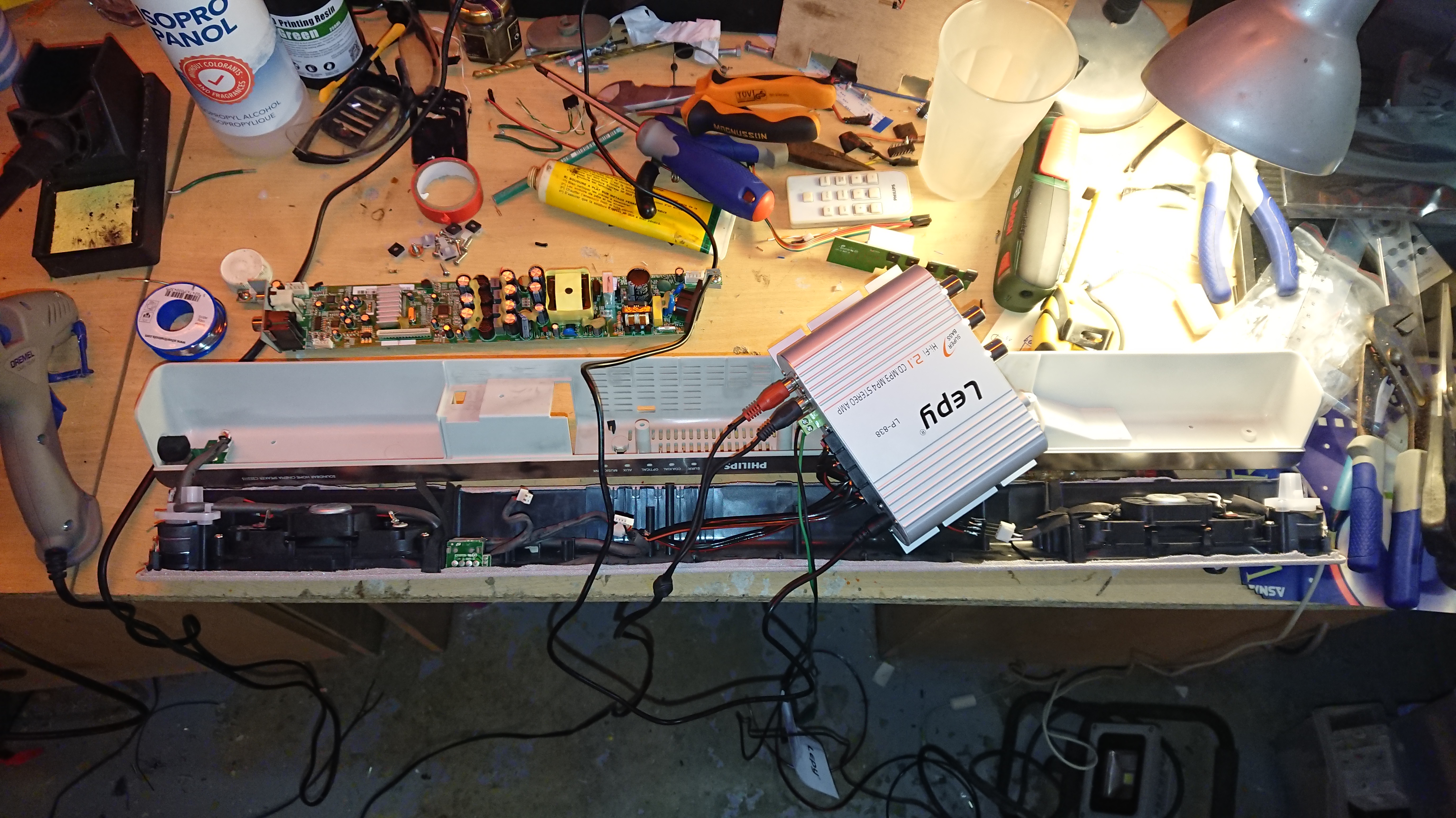
Fixing the audio bar
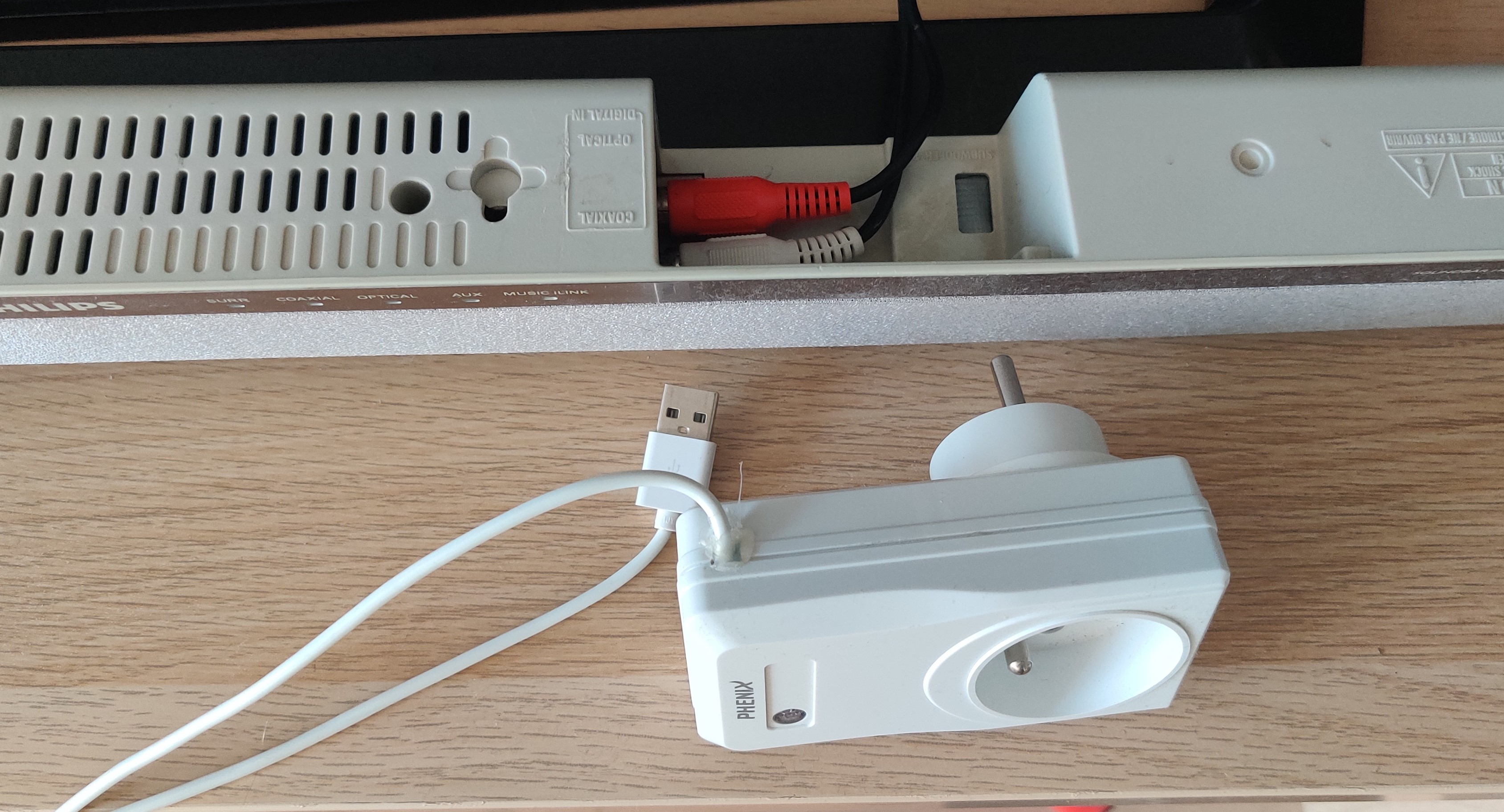
My Phillips audio bar also stopped working after some time, so I decided to fix it. As I don’t have a lot of knowledge about electronics I wasen’t able to identify the faulty component on the board, so I simply ordered a cheap 2.1 amplifier. As this ampifier wouldn’t fit into the bar, I rewired the bar’s speakers to RCA plugs on the bar and then used these plugs to connect the bar to the amplifier.
But there was no remote with this amplifier, it’s not much of a problem for the volume (as we can still adjust it from the tv) but it isn’t practical to power it on and off. So I created a simple plug with a 230v relay powered by a usb port. The usb plug is connected to the TV, so when the TV is powered on, the usb ports will also be powered, which will then power the relay and let the current pass to power the amplifier.
Conclusion
We have seen 2 different methods to create an amibilght system and especially to capture video, both of them having their advantages and drawbacks.
The second one requires less hardware and space but you need to install a client software on each device that you want to use (and some devices will just not work like the PS4 where you can’t install anything), moreover you can only use this method to capture unprotected content.
In contrast to this, the first method, while requiring significantly more hardware, will likely allow you to capture pretty much anything and once the first setup is done, it should be only a matter of plugging the device on the HDMI switch to add a new device.
So, in the next version (an hopefully the last one), I think that I will use a bit of both methods with a standalone capture device like in the first method based on a raspberry pi and either an RCA grabber or directly with a CSI-to-HDMI adapter, and a command part kept as is, with the ESP8266 that allows to control the tv and the leds from Hyperion or directly from Home Assistant.