Easily create you DIY IoT devices with ESP Home and Home Assistant
When I started to tinker with home automation and electronics a few years ago, it was common to use arduino cards to create DIY connected devices. You would then communicate with a central server to send and receive information. The communications were usually done using usb, ethernet (using an ethernet shield) or radio (2.4Ghz or 433Mhz) with projects like MySensors.
Most of the time these cards were programmed using the “Arduino language” which is quite close to C++. I kept this habit when I switched to use the esp8266/esp32 cards but in the meantime, awesome projects were developped to facilitate the development of this kind of devices, especially dedicated ecosystems like ESP-Easy, Tasmota and ESP Home, which is the project that I decided to use.
Why ESP Home ?
While Tasmota and ESP-Easy are “battery-included” firmwares that you flash on the esp board and then configure with a web ui, ESP Home compiles a firmware specially for your device based on a yaml configuration file that tells it which kind of technology (SPI, I2C, UART) and sensor (dht22, HC-SR04 …) you are using and on which pins they are accessible. It even allows you to manally add C++ code through “lambdas”. Another great point of ESP Home is the native integration to Home Assistant (a very powerful home automation system) so we can focus on actually creating our IoT device instead of bothering about communication with the server. So let’s get started !
Getting started with ESP Home
While this is not mandatory, I would recommend to install the ESP Home server using the docker image, which will facilitate the development of our devices with a user friendly web interface. (You can also skip this step and use directly ESP Home in CLI). So, I created the following docker-compose file to start the esphome dashboard and access it using traefik. I also decided to use ping instead of mdns to check for device status.
version: "3"
services:
    esphome:
        image: esphome/esphome
        environment:
            - TZ=Europe/Paris
            - ESPHOME_DASHBOARD_USE_PING=true
        volumes:
            - /app/docker/data/EspHome:/config
        restart: unless-stopped
        labels:
            - traefik.http.routers.lan_esphome.rule=Host(`esphome.domain.tld`)
            - traefik.http.routers.lan_esphome.entrypoints=https_lan
            - traefik.http.routers.lan_esphome.middlewares=authelia_lan
            - traefik.http.routers.lan_esphome.tls=true
            - traefik.http.services.lan_esphome.loadbalancer.server.port=6052
            - traefik.enable=true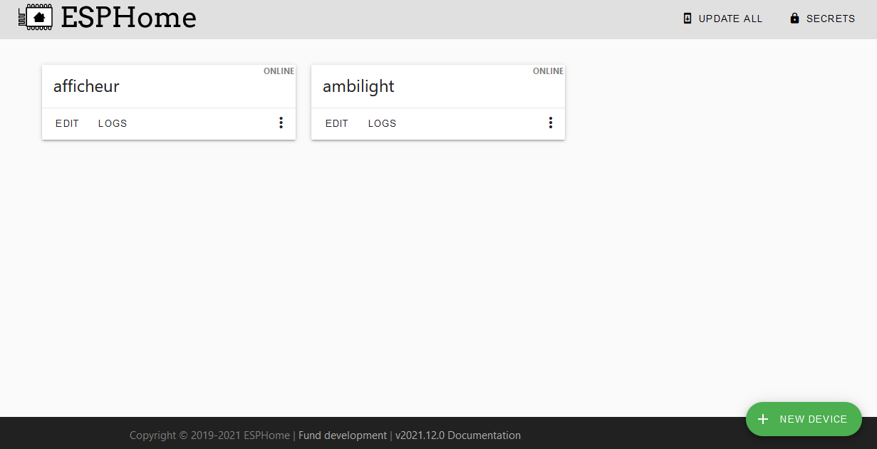
You now have access to your ESP Home dashboard and can create a new configuration by clicking on the “NEW DEVICE” button. You will then have to enter some information about your device and a default configuration will be generated.
esphome:
  name: test

esp8266:
  board: esp01_1m

# Enable logging
logger:

# Enable Home Assistant API
api:

ota:
  password: "ff16ebc60e9b22668b2e6fff77e6636f"

wifi:
  ssid: !secret wifi_ssid
  password: !secret wifi_password

  # Enable fallback hotspot (captive portal) in case wifi connection fails
  ap:
    ssid: "Test Fallback Hotspot"
    password: "mfp7hXdwozmk"

captive_portal:
You should have something like this. The captive_portal and ap configuration will allow you to reconfigure your device in case your wifi is no longer available. The “normal” connection to your wifi is configured with the ssid and password keys. The !secret refers to the data stored in the secrets section (in the top right corner of the ui). In there you can configure your wifi credentials like this:
wifi_ssid: yourssid
wifi_password: yourpassword
You now have the basic configuration needed to flash your device, we will now add the specific configuration to register your sensors.
Create your first IoT device
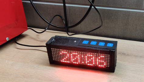
Here’s the device that I will make: a simple display based on 4 8x8 matrices in a wooden enclosure painted in black.
The device will also have a photoresistor to adapt the brightness of the matrices and a row of 4 buttons to trigger some actions on home assistant. Everything is wired on a node mcu (with an esp8266).

esphome:
  name: afficheur
  platform: ESP8266
  board: nodemcuv2

# Enable logging
logger:

# Enable Home Assistant API
api:

ota:
  password: ""

wifi:
  ssid: !secret "wifi_ssid"
  password: !secret "wifi_password"

  manual_ip:
    static_ip: 10.20.8.1
    gateway: 10.20.1.1
    subnet: 255.255.0.0

  # Enable fallback hotspot (captive portal) in case wifi connection fails
  ap:
    ssid: "Afficheur Fallback Hotspot"
    password: ""

captive_portal:

status_led:
  pin: D4


#===================== display data =============================

font:
  - file: "pixelmix.ttf"
    id: digit_font
    size: 8

time:
  - platform: homeassistant
    id: hass_time

globals:
  - id: new_text
    type: int
    initial_value: "3"
  - id: txt_cycles
    type: int
    initial_value: "1"
  - id: screen_status
    type: bool
    initial_value: "1"

text_sensor:
  - platform: homeassistant
    name: "afficheur texte"
    entity_id: input_text.afficheur_txt
    id: txt
    on_value:
      then:
        lambda: |-
          id(new_text) = 0;

#===================== display settings =============================

spi:
  clk_pin: D5
  mosi_pin: D7

display:
  - platform: max7219digit
    cs_pin: D8
    num_chips: 4
    rotate_chip: 90
    id: matrixdisplay
    intensity: 4
    scroll_speed: 50ms
    scroll_mode: STOP
    update_interval: 3s
    lambda: |-
      if (id(new_text) <= id(txt_cycles)) {
        if(id(new_text) == 0) {
          id(txt_cycles) = ceil(strlen(id(txt).state.c_str()) / 6);
        }
        it.printf(0, 0, id(digit_font), "%s", id(txt).state.c_str());
        id(new_text)++;
      } else {
        it.strftime(0, 0, id(digit_font), " %H:%M", id(hass_time).now());
      }


#===================== display control =============================

number:
  - platform: template
    name: Screen Brightness
    min_value: 0
    max_value: 15
    step: 1
    set_action:
      then:
        lambda: |-
          id(matrixdisplay).intensity(x);

switch:
  - platform: template
    name: Screen Enable
    lambda: |-
      return id(screen_status);
    turn_on_action:
      then:
        lambda: |-
          id(matrixdisplay).turn_on_off(true);
          id(screen_status) = 1;
    turn_off_action:
      then:
        lambda: |-
          id(matrixdisplay).turn_on_off(false);
          id(screen_status) = 0;

#===================== sensors =============================

sensor:
  - platform: adc
    id: source_sensor
    pin: A0

  - platform: resistance
    sensor: source_sensor
    configuration: DOWNSTREAM
    resistor: 10kOhm
    name: Resistance Sensor

binary_sensor:
  - platform: gpio
    pin: D3
    name: "Btn 1"
  - platform: gpio
    pin: D2
    name: "Btn 2"
  - platform: gpio
    pin: D1
    name: "Btn 3"
  - platform: gpio
    pin: D0
    name: "Btn 4"
This is the full code for our display.
I defined a status led wired on pin D4 to have a quick indication of the status of the connection (the led itself is located on the back of the display).
In order to display text, you will need to configure a font, here I am using the pixelmix.ttf file that you can download here. You then need to place the font file in the same directory of your config file (in my case /app/docker/data/EspHome, see the docker-compose file).
As I want to use the display as a clock when I have no message to show, I defined a time section with home assistant as the source. I also define 2 global variables to help to switch between the “message mode” and the “clock mode”, and a text sensor to allow home assistant to send a message to display (NB: the text sensor also needs to be created manually on Home-Assistant as a text helper, with the same entity id).
My matrices are of type max7219. They communicate using SPI, so I defined a spi section with the clk and mosi pins. I can then define a max7219digit component and specifiy the CS pin. The num_chips key indicates the number of matrices that I have connected, here 4. I used custom C++ code to define the message to display using the lambda key. This code displays the message from the text sensor if it has changed or defaults to a clock. The display is refreshed every 3 seconds.
I also defined 2 template switches: a slider to control the brightness of the matrices from home assistant and a switch to turn on/off the display.
For the sensors part, I defined an adc component with the pin A0 where my photoresistor is connected and a resistance component that converts the voltage to resistance and reports it to home assistant. I also defined 4 binary sensors for the buttons disposed on top of the display.
Flashing the ESP
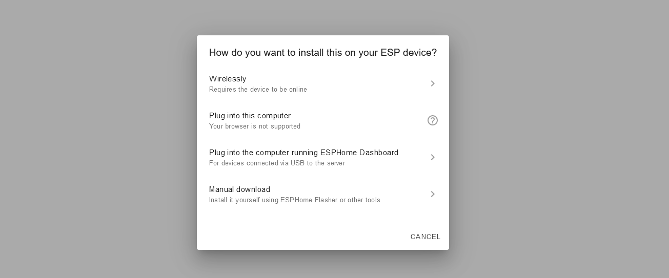
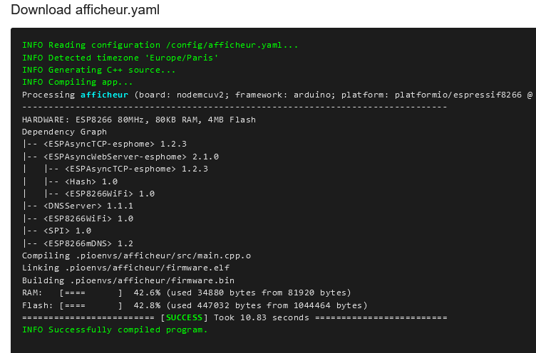
To flash your esp click on the install button. For the first time I recommand to use the Manual Dowload option and use ESPHome-Flasher (you can also flash it using a chrome-based browser but it will be slower). Futures updates can be done via OTA so you will only need to plug your device to your computer for the first installation.

You are now ready to go ! Your device will connect to your wifi and should appear in the device section of home assistant.

I would highly recommend ESP Home as it is a really interesting framework to create specific firmware for your IoT devices. It also allows a great saving of time compared to the development of a custom firmware in C ++ “from scratch”. So I can only recommend to check out their website for more information.